

Last month we continued with our coverage of Close Control Air Conditioning. This month we continue to look at the benefits of Free Cooling as related to Close Control Air Conditioning Applications and environments.
Packaged Units
These have a number of feature including DC Driven Fan Motors for back up supply by means of the DC batteries strapped on to the container. A rectifier-inverter takes the normal AC supply and converts this to DC for normal operation.
The standard control regime is based upon electro-mechanical controls. This ensures that in areas predominantly of an export nature, a greater tolerance to voltage fluctuation and a continuation of unit operation under these potential conditions. As an option, a micro-processor can be fitted for areas where the power supply is more reliable.
Chilled Water Units & Free Cooling advantage using Chillers
We have taken the following formats and features of the Clivet-Isovel Ltd indoor units to serve as a guide of the equipment alternatives and systems available.
The Clivet-Isopak series of chilled water air conditioning systems has been designed to ensure that precise environmental conditions are maintained over a broad range of operating parameters. Three versatile and distinct Isopak system types with cooling capacities from 5kW to 120 kW are available to suit a wide spectrum of specifications. Each system occupies a small floor area and has unsurpassed features and performance.
Isopak MR
Designed to suit the requirements of the smaller conditioned space with 3 models available in both upflow and downflow supply air arrangement.
Isopak FR
The Isopak FR is a mid-range cooling capacity series with 3 models suitable for upflow airflow distribution and is ideal for ducted supply applications or where underfloor air distribution is not available.
Isopak VR
The Isopak VR meets the demands of the smallest to largest conditioned space. 3 models are included in the range, all of which are manufactured in either upflow or downflow airflow configuration.
The free-cooling chiller that would be matched with the above will give considerable energy savings and benefit to the running costs of that installation.
Conventional Application of Chilled Water & Chiller – without Free Cooling
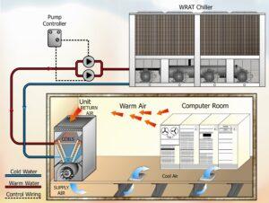
Diagram 1 – WRAT Chiller. Conventional Application of Chilled Water & Chiller – without Free Cooling. Courtesy Clivet-Isovel Ltd.
Diagram 1 shows a standard application of a chilled water unit in room which is matched to an external outdoor chiller. Conventionally, dependant upon the site application, this unit will run for 365 days of the year, 7days per week, 24 hours per day. Thus, the chiller associated with this unit will have to provide chilled water at a specific temperature throughout the year. Hence, without free cooling, maximum power is absorbed with no potential of reducing this demand.
The following systems seek to provide benefit to the system owner by substantially reducing the annual energy consumption through free cooling.
Conventional Application of Chilled Water & Chiller – with Free Cooling
Conventional Application of Chilled Water & Chiller – with Free Cooling. Courtesy Clivet-Isovel Ltd.
As shown in Diagram 10, we now detail a free cooling coil and associated control valve arrangement which seek to secure running cost advantages through external low ambient dry bulb temperatures.
Free Cooling Chiller – Dual Circuit Application – Operating Principle
Free Cooling Chiller – Dual Circuit Application – Operating Principle. Courtesy Clivet-Isovel Ltd.
Superchiller is a compact, packaged water chiller comprising:
- One or more refrigeration circuits with air-cooled condenser(s);
- A system of pre-cooling and cooling the water using ambient air (’free-cooling’) when the latter is at a temperature below the return water temperature;
- A control system to optimise operation for maximum energy-saving at all times;
- An assembly comprising circulating pump(s), expansion tank, isolating valves, water connections and electrical controls (optional). All these components are fitted to provide a unit which is completely factory assembled and tested, ready for installation at minimum cost.
Diagram 2 illustrates the principle of operation:
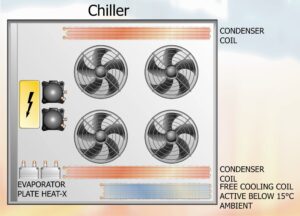
Diagram 2 – Chiller Plan View
- The water to be cooled (returning from the machine or process in which it has been used) is pumped by the circulating pump, through the three way valve to the heat exchangers, where it is cooled by the evaporating refrigerant.
The refrigeration circuit basically comprises compressor(s), condensers cooled by an ambient airstream provided by fans, refrigerant expansion valve(s) and evaporator(s).
When the outside air temperature is below the return water temperature to the SUPERCHILLER, the three way valve, operated by a differential thermostat, diverts the water flow through the water-to-air heat exchangers (to obtain the ‘free cooling’ effect) before it passes to the water-to-refrigerant heat exchangers.
If the outside air temperature is sufficiently low to dissipate all the heat necessary, the refrigeration compressors are automatically switched off, and control of the chilled water temperature is effected by cycling of the fans and this is the only electricity consumption.
If the outside temperature is not low enough to provide all the cooling, the compressor(s) will switch on only for as long as is necessary to ensure the correct chilled water temperature thus reducing energy consumption.
The efficiency-conscious design of the Superchiller makes it possible to dissipate the heat load utilizing Free Cooling, the unit’s refrigeration circuit, or a combination of both.
The water/glycol mixture to be cooled (returning from the machine or process in which it has been used) is pumped through the three-way valve to the evaporator, where it is cooled by evaporating refrigerant.
The refrigeration circuit includes compressors, condensers, an ambient air stream introduced by fans, refrigerant expansion valves, and evaporators.
When the outside air temperature is below the temperature of the water/glycol mixture returning to the unit, the three way valve, operated by a differential thermostat, diverts the mixture flow through free cooling heat exchangers. This creates the free cooling effect.
If the outside temperature is sufficiently low to dissipate the entire heat load, the refrigeration compressors automatically switch off, and the mixture’s temperature is controlled by the ON/OFF sequence of the fans.
If the outside temperature is too high for free cooling, the compressors will operate for as long as is necessary to ensure the correct glycol/water mixture temperature.
Note: Single Circuit application is available generally as per the Dual Circuit System outlined above to allow similar financial benefits on small chilled water installed systems.
NOTE: Our sincere thanks go to Mr. Patrick Murphy, Sales Director Clivet-Isovel Ltd for his valuable contribution in terms of content, technical data and illustrations. Editing by Mike Creamer of Business Edge Ltd. Re-creation of Drawings by Business Edge Ltd.
DISCLAIMER: Whilst every effort is made to ensure absolute accuracy, Business Edge Ltd. will not accept any responsibility or liability for direct or indirect losses arising from the use of the data contained in this series of articles.