

In last month’s article we concluded the series of articles covering close control air conditioning and free cooling. In this months journal we begin a series of articles looking at Reverse Cycle Water Source Heat Pumps.
THE REVERSE CYCLE WATER SOURCE HEAT PUMP SYSTEM
In this article we look at the principle of the system along with its applications and advantages, followed by an overview of system design, unit selection and the control of the water loop system.
INTRODUCTION
The Reverse Cycle Water Source Heat Pump system provides an energy efficient, environmentally friendly system.
In a basic air conditioning system the heat within a given space is rejected to atmosphere via a refrigerant based air-cooled condenser, therefore offering no energy reclaim benefits.
The Reverse Cycle Water Source Heat Pump system employs water is as a transfer medium and is maintained within a predetermined operating band by means of a form of heat injector or rejecter. The systems use of ground loops in Geothermal applications means that the water loop temperature is controlled within a predetermined band providing individual units with a transfer medium to allow heating and cooling on an independent basis.
This forms an energy efficient heat transfer system which, assuming the system is within the dead band of operation, requires no form of heat injection or rejection. It has been proven that for 60% of the year the Heat Pump system can run in a thermal balance situation, thus minimizing running costs by using pre-paid energy.
The system may incorporate any number of individual self-contained water source heat pump air conditioners, connected to a simple two-pipe closed water loop system. This system of air conditioning offers the installer and end user total flexibility with individual unit control, adaptability, energy efficiency, simplicity of servicing, fast track installation and low running costs. It also offers environmental benefits with a minimal quantity of non-ozone depleting refrigerant, hermetically sealed within each heat pump. This eliminates the need for any on site refrigerant handling and as the refrigerant is factory encapsulated, minimilises the possibility of any leakage. A further advantage is the fact that the system is extremely simple to design and requires only basic pipe work skills for the mechanical installation.
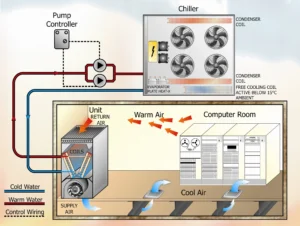
Fig 1 Chiller Free Cooling
CONTROL FLEXIBILITY
The system’s flexibility enables the occupants of the air-conditioned areas to have individual control of their working environment, irrespective of the requirements of the occupants of adjacent rooms. This type of system also has the advantage that in the very rare event of a unit failure, the breakdown does not affect adjoining areas and does not involve shutting down the entire system as may be the case in the event of a fault in a central plant or multi split type air conditioning system.
The popularity of zoned air conditioning, which allows any room to be air-conditioned independently and tempered to meet requirements different from adjacent areas, contributes to the overall running economics of the system. Many older type hotel and office buildings are being renovated and modernised to meet present day standards. Such renovation and modernisation has to be carried out in most instances whilst the building is at least partly occupied. It is, therefore, essential that the installation of an air conditioning system or plant should be effected with as little disruption to the building or its occupants as possible. Because of its simplicity of installation and its’ use of small-bore uninsulated pipe work and minimal size ductwork, this type of system has many advantages in reducing the installation disruption to a minimum. This can often be an overriding factor when considering air conditioning for buildings such as an hotel, where the system may be installed and operated on a phased basis.
Another consideration is that many older type buildings the existing available plant room space is restricted and in new or modern buildings it is always desirable to keep the plant room to a minimum. The Heat Pump system ideally lends itself to these requirements, as not only is the plant compact but in the older type buildings some of the existing services such as boilers, and in some instances pipework, may be incorporated.
SYSTEM OPERATION
The system comprises a number of reverse cycle heat pump units interconnected by a two-pipe closed water loop, within this loop are installed supplementary methods of heat rejection and heat injection. The two-pipe water loop is maintained within a controlled temperature band thus providing a heat source or sink from which the reverse cycle heat pumps draw heat or conversely into which they reject heat.
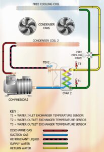
Fig 2 Chiller Pipework Schematic
In winter, when a majority of units may be providing heating, the heat being drawn from the water loop may eventually depress the loop temperature below the design limit. Supplementary heat injection would then be activated to raise the loop temperature back to the design temperature band.
Conversely, in summer, when a majority of units may be in cooling, rejecting heat into the water loop, the loop temperature would eventually exceed the design conditions. The method of heat rejection, i.e. dry cooler or similar, would then be activated to reject the excess heat from the water loop and return it to the design temperature band.
From the above explanation it can be seen that only the supplementary heat injector or the heat rejecter, operates at any one time, never together, unlike a fan coil type systems where a boiler and chiller would run simultaneously to provide independent cooling and heating.
During the intermediate seasons of the year, i.e. for approximately 8 months of annual operation, the heat rejected by the units operating on cooling is used by those units operating on heating. Thus a thermal balance is attained across the system and neither the heat rejecter nor heat injector is required to operate.
The unit comprises a hermetically sealed refrigeration circuit with refrigerant-to-air and refrigerant-to-water heat exchangers. The refrigerant circuit is reversed automatically by the user-set thermostat, such that each heat exchanger acts either as evaporator or condenser. The air side heat exchanger provides heat or cooling to the room by passing air over the indoor coil, whilst the water heat exchanger either extracts heat from the water or rejects heat to it.
Each unit requires an electrical supply, a condensate drain and connections to the flow and return of the water loop.
NOTE: Our sincere thanks go to Mr. Patrick Murphy, Sales Director Clivet-Isovel Ltd for his valuable contribution in terms of content, technical data and illustrations. Editing by Mike Creamer of Business Edge Ltd. Re-creation of Drawings by Business Edge Ltd.
DISCLAIMER: Whilst every effort is made to ensure absolute accuracy, Business Edge Ltd. will not accept any responsibility or liability for direct or indirect losses arising from the use of the data contained in this series of articles.