

These systems revolve around the use of cold water and some form of atomisation. Some degree of water treatment and a maintenance regime is desirable to extend the life of the plant and deal with health and safety issues that surround these type of systems. Like all types of system if they are designed, installed and maintained correctly they will give good long-term operation. The alternatives available include:
- Sprays
- Ultrasonic systems
- Spinning disc
- •Evaporative
Air pressure spray system
These systems have developed out of the spray washer that is still used for some industrial processes. These tended to operate using a simple pressurised water supply to an atomising head and spray into the air stream normally against the cooling. This would be prone to clogging and the performance was generally considered to be poor.
Compressed air has now been introduced which dramatically increases the agitation of the water to create a very fine mist that does not depend on a blanket, in the form of the cooling coil, to help absorption. The introduction of compressed air has so advanced the atomisation process that some manufacturers have described it as ultrasonic.
The effect is that the water is broken up into a very fine aerosol. The capability of water-borne minerals to block the fine nozzles is reduced by the speed of the water passing through the system.
These systems can use raw or base exchange treated water but would then emit quantities of minerals into the air stream, which suggests that they are more suited to de-mineralised water feed. These systems can be used in ducted systems or space application. There must be full water conditioning and control to prevent the development of Legionella bacteria throughout the system. These water treatment measures are fully described in the Health and Safety Document ‘Approved Code of Practice and Guidance’ for the control of Legionella in water systems. The Humidity Group, part of the HEVAC Association has also published a Code of Practice for the design maintenance of such cold-water adiabatic systems.
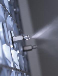
Fig 9 – High pressure nozzle
The heart of the system is the nozzle, which would normally have an automatic cleaning cycle to keep the orifice clear and free of mineral build up. The nozzle material can be brass or stainless steel dependent on the water quality being used in the application. The same nozzles would be used in the ducted and space application.
The ducted application mounts a number of nozzles onto a header bar positioned across the full width of the air path. There could be multiple headers offset from each other dependant on the capacity required. Eliminators are normally positioned downstream of the calculated absorption distance to ensure no carryover of water occurs.
The space application would have a range of single and double nozzle header arrangements that can be rotated for directional purposes. Each header arrangement would be mounted at high level around the space to ensure all the area is covered. The space application does not rely on an air path for dispersion. Water vapour will disperse naturally form a high to a low moisture content without the aid of forced ventilation.
Control of the space system would be by a single humidistat in a designated area or an averaging arrangement across the whole area. Whichever is used it will be relatively crude control but the application would not warrant a high degree of sophistication.
Ultrasonic spray system
The ultrasonic system use transducers oscillating at a frequency of 1.7 MHz to atomise water into an aerosol, which is then passed into the air-stream. Each transducer has a nominal output of approximately 0.6 kg/hr, which requires a considerable number to produce a reasonable output.
There are two types of device available, one sits in the air stream and utilises the system air movement, and the other sits outside and pipes the moisture into the space and includes a fan arrangement within its own cabinet.
The in-duct device has aerodynamic hoods over each transducer well, the open end facing in the direction of the airflow. The atomised water is induced out to entrain with the air prior to the next element in the air path. The ‘fog’ produced by this device is very fine and will be absorbed very quickly into the surrounding air.
As with all cold water systems the ultrasonic unit is best served with de-mineralised water to ensure no mineral particles either entered the air stream or clogged the transducer well. Again there must be conformance to the Code of practice governing the Legionella bacteria. This would require regular draining of the well if left inoperable for lengthy periods.
The second type is a self contained device that can be used to duct the ‘fog’ into an air stream or into a space. Because it is a cold water ‘fog’ and heavier than surrounding air it will have a tendancy to fall to the floor unless supported by an air flow.
These devices have been used in air conditioning plant as well as horticultural and food humidification application. The very fine mist would be absorbed into the surrounding air quite quickly although eliminators are sometimes used to ensure no carry over.
Relatively expensive to buy compared to the other systems but very cheap to run as a stand alone humidifier. If water treatment such as softeners, de-mineralisation and or ultraviolet light is required the initial cost as well as run costs will increase. As with all adiabatic systems the re-heat, if required can offset the run cost benefit accrued with this technology.
Spinning disc
The spinning disc type of unit introduces droplets of water onto the face of a rotating disc. This representation shows a horizontal disc, centrifugal force spins the droplets to the perimeter through the teeth and into the air stream as a mist. There are variations to this theme where the disc is vertical and rotates at high speed into a shallow bath of water. Another rotates a drum at high speed around a spray nozzle. Control is relatively course and would normally be controlled by varying the volume of water introduced. De-mineralised water would be the most appropriate water supply for this type of adiabatic system.
The bench mark London water would require some serious filtration before the air is introduced into the space or water treatment to get rid of the dusting before it becomes a maintenance problem. Ducted and space applications can be considered from relatively low to high capacity ratings although the system does lend itself to the larger application.
Relatively cheap as a first cost and cheap to operate and run. The expense will come with the water treatment to prevent dusting plus the health and safety regime required with all cold water systems. Again re-heat may also have to be considered dependant on the application.
Evaporative : Wetted media
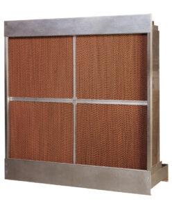
Fig 10 – Wetted Media
The evaporative system feeds water to the top cell structure, which then precipitates through the media. Air flowing through the media evaporates the moisture and takes it up into the air stream. This is quite an uncomplicated system to install and operate and tends to come as a self-contained cartridge that includes the cell material, water bath, pump, supply and drain controls. There are a number of different cell materials available and would depend on the type of application including the air that would pass through the structure. A good reliable media would be glass fibre treated with wetting agents that are non-toxic and non-organic.
The water supply should be filtered as a minimum consideration as should the air to prevent build up of contaminants within the bath or on the cell structure. An ultra violet lamp to the supply water ensures the water is sterile when introduced into the reservoir. Using de-mineralised water could be counter productive as it will be quite aggressive and attract air born minerals and contaminants that could develop into long term maintenance issues.
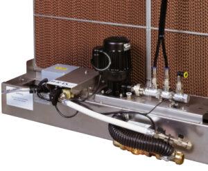
Fig 11 – Wetted Media Pump
The system would be constantly replenished with fresh water over and above the evaporation rate and incorporate a bleed mechanism The cell is kept wet at times of humidification, which has the effect of constantly washing the cell media to prevent a build up of contaminants or micro-organisms.
These systems are available for medium to large applications and are best suited to the industry process application where large amounts of air are required especially if washing or scrubbing action is required for the supply air.
Again relatively cheap as a first cost base item, the water treatment adding considerably to the system cost. Cheap to run although allowances should be made for major cleaning or replacement of the cell material after a number of years operation. The intervals would depend on the water and air quality, the manufacturer would give recommendations given the design conditions and water / air qualities being dealt with.
Humidity control
The statement that occurs time and again is that temperature and moisture content, whether in absolute or relative terms, are linked and cannot be seperated. We can sum this statement up with another rule of thumb: A temperature difference of 1.5oC affects a target humidity of 50% by about 5% RH. So when we specify 21°C DB +/- 2 degrees C and 50% RH +/- 5% Relative Humidity we are defining quite a considerable area of control as indicated on the Control Parameter Psychrometric Chart. We have not taken into account any accuaracy deviations that will occure with whatever type of control sensor we choose.
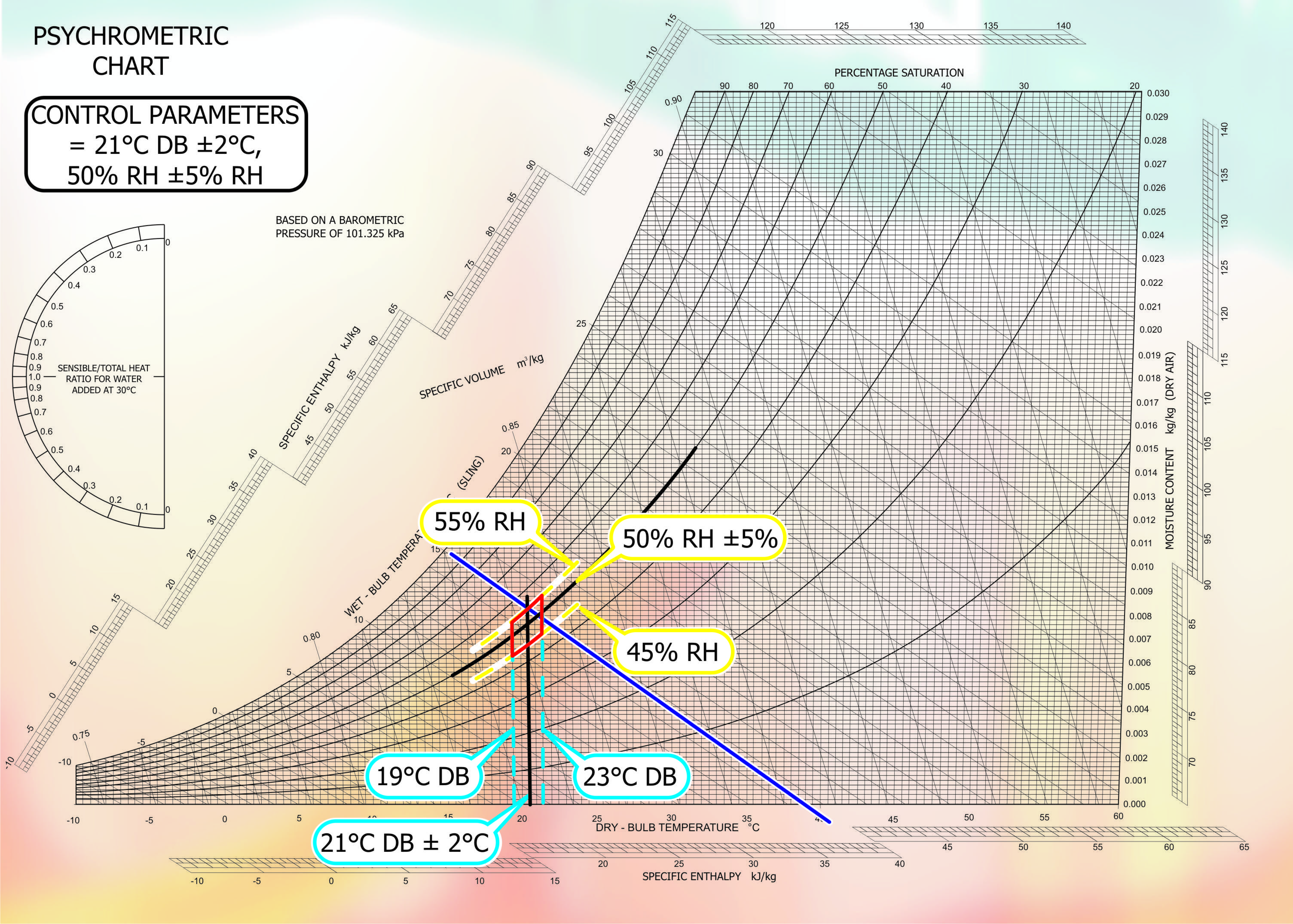
Fig 12 – Control Parameters
To control the humidity level we must first measure the amount of water vapour present in the air at the sensing point. There are two main types of sensor used: Dew Point Sensor tells us at what temperature condensation will occur if the air is cooled and is a measure of how much water vapour the air holds in absolute terms. The second is the Relative Humidity Sensor which measures the degree of saturation of the air on a scale of 0 to 100%. This device is dependant of temperature as well as moisture content. It is more common the use the RH Contoler in commercial applications and the Condensation Hygrometers in very close control applications or as a reference sensors for calibration purposes.
Mechanical controller
The oldest devise for humidity control would be with a simple humidistat. This would be a single step mechanism that would probably utilise either horse or human hair to operate a switch. Both these materials are hygroscopic and lengthen or shorten with changing humidity levels. Relatively course control and are used for high or low limit safety devices within an uncomplicated control scenario. Times have moved on and electronic devices are more prevalent and can be split into two camps.
Electronic controller
The Capacitive device has a control band of 0 to 95% and the resistive, which has a band of 25 to 95%. All RH controllers whether mechanical or electronic have problems controlling at 95 to 100% RH and it is normal to use the Dew Point or Condensation Hygrometer for these high limits.
Psychrometer
The sling psychrometer tends to be used to measure or check internal or external conditions. Using a wet and dry bulb thermometer, they are rotated or exposed to an air velocity, readings taken and plotted onto a psychrometric chart. Used in weather stations to measure maximum and minimum prevailing conditions. Electronic devices that do offer a more accurate measurement with the added benefit of being able to be re-calibrated are superseding these.
Location
As with temperature controllers or sensors the position is of paramount importance. The space controller/sensor needs to be positioned to reflect the prevailing condition within the space. This could be mid way between the supply and return air points. This can be further complicated if there are multiple points of entry and exit, so the safe bet is to choose a point in the return air path as close to the temperature controller as possible. Keep it away from any external influences such as;
Solar effects – Direct sun light will give erratic performance of the system as the sun moves around the building. Difficult to diagnose when looking for reasons for bad performance.
Draughts – Supply air diffuser that may blow air directly over the sensor. The temperature gradient across the space will not be picked up if the control point is the supply air condition. There will be a further effect of air velocity over the sensor, which would take it outside its operating limits.
Equipment – Radiators, Drinks machines, Office equipment giving off heat, all of these will create a micro climate within the space that by its shear nature will not reflect the prevailing condition.
External Surfaces – This could be more difficult to ensure against. Insulating the sensor from the influence of the cold or warm surface is a possible way of limiting this factor
Mounting the controller / sensor in the return air duct is another safe decision, but care must be taken to introduce an off set for the condition gradient across the space. There could be multiple return air points all converging on a common return air duct. A good averaging point, but bear in mind it will be an average not a specific condition, we move back to the science of the predicted percentage of dissatisfaction discussed earlier. Multiple sensing points will increase our ability to average or introduce supply air control into each space or zone. The common factor as we move through all the more elegant solutions is that the price goes up proportionally. Not necessarily what the client wants to hear.
High limit overrides, mounted in the supply duct, should be positioned to prevent over humidification leading to wetting out within the air handler or supply air duct. A good rule of thumb is minimum of four to five metres of duct from the point the moisture is introduced. Avoid dead spots in the ductwork and if possible ensure the moisture is fully absorbed into the supply air.
Calibration
All sensors will drift out of calibration over a period of time typically three to five percent. They can also suffer from some of the following ailments
- Poor repeatability in the short term.
- Slow response time
- Hysteresis or memory effects
- Coarse resolution
Regular calibration checks will identify bad sensors and with the right action will improve the system performance. These measures would be:
Start calibration checks with short time intervals then reduce frequency as confidence builds in the equipment installed.
Compare with a reliable calibration reference, typically one supplied by a United Kingdom Accreditation Service (UKAS) test laboratory.
Using a UKAS laboratory ensures the technical competence and proficiency of the service. There is traceability to national standards that will also meet quality management standards, ISO 9000, and a demonstrable audit trail resulting in increased confidence that the system will operate within the design criteria laid down at the start of the project.
Energy Usage
Uncertainties in the control equipment can add up to an increase in run costs for the system and building. These uncertainties would depend on the operation and calibration of the measuring equipment, the fluctuation in the humidity during its cycle of operation and the condition gradient across the space or zones. The National Physical Laboratory calculates these uncertainties, on a theoretical base, using the following criteria
Say the calibration uncertainty at 50% RH was +/- 2% the real uncertainty in using the device after allowing for intrinsic drift, repeatability, hysterisis, resolution, etc is +/- 3%
Say the room is cycling up and down by +/- 3%
Say there are differences across the space of +/- 5%
Lets say the above can be added up by taking the square root of (3)2 + (3)2 + (5)2 = 6.6.
We are reasonably sure the true humidity at any spot in the space is between 43.4% RH and 56.6% RH.
If we take this theoretical control shift or sensing error and equate it to a theoretical build of say 5000 m3 with a design set point of 22oC DB / 50% RH. If we apply our 6.6% shift so the measured set point is 22oC DB / 56.6% RH there is a possible 33% increase on run cost for an electrode boiler humidifier. One must off set the possibility the shift is in the other direction and the measured set point is 22oC DB / 43.4% RH, in which case there would be a 33% reduction in cost. It’s all down to whether the sensors are measuring predominantly high or low.
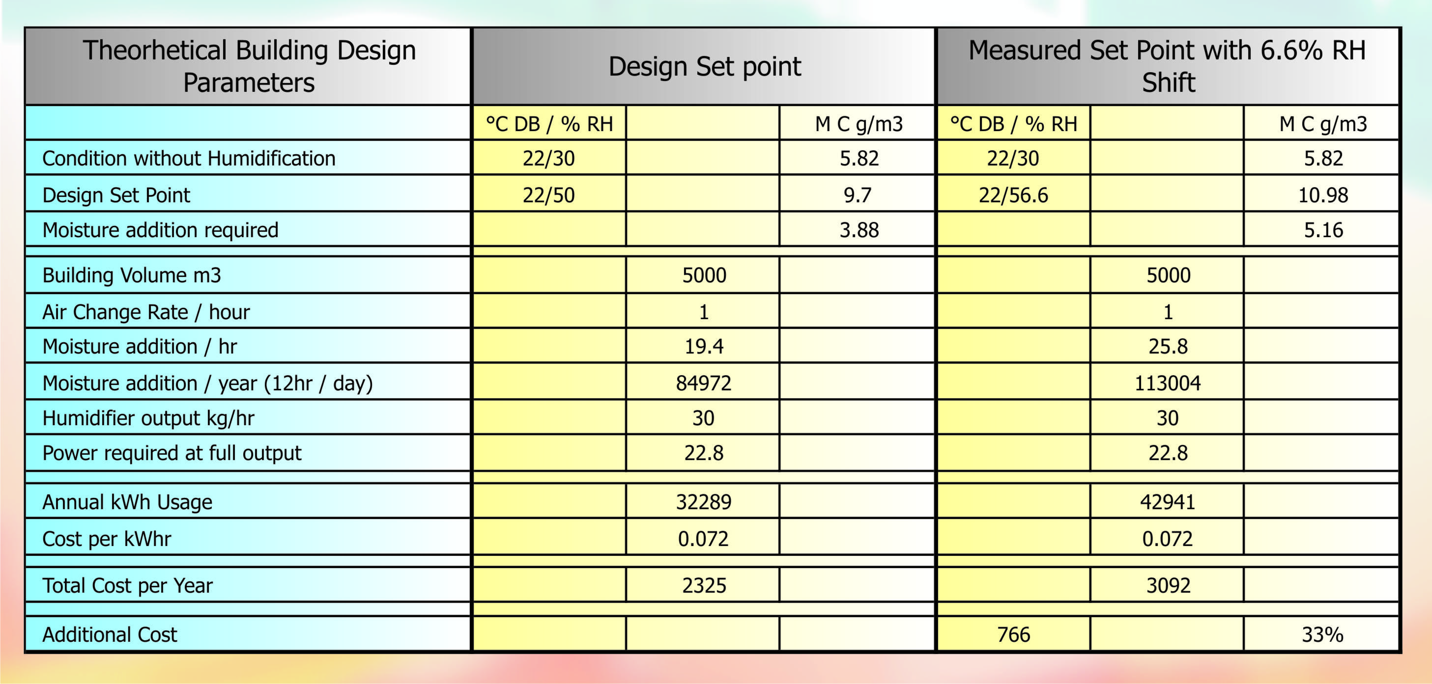
Fig 13 – Humidification Cost
Comparative run costs
This final section covers comparative running costs over the 15-year life span one should expect from capital plant and looks at four different capacities. The comparison of systems within the Isothermal family include electrode and element boilers, local and centrally generated steam from gas fired equipment units compared are electrode boilers, element boilers, central steam generators. The wetted media and spray systems represent adiabatic family.
Calculation data
The information used to generate comparable figures are:
15-year life span for the equipment, 30, 60, 200 and 400 kg/hr Humidification load,
Winter heat operation with the system designed to be recirculating nominally 90% with 10% outdoor-air intake. Hours run figures are based on 30 weeks per annum, with 60% diversification, five days per week and 10 hours per day. The calculations have used electrical power at six pence and gas at .01 pence per kW.
Each comparison includes allowances for spare part, maintenance, service and ancillary equipment that would not be normally included in commercial office building. The costs also include for re-heat in the case of adiabatic systems as the design criteria is 22oC DB / 50% RH
Electrode Boiler
Operating on raw London water and includes three replacement cylinders per year plus the manufacturers recommended maintenance intervals.
Resistance or Element Boiler
Assumes base exchange treated water is available on the same London site and include the normal maintenance periods for this type of unit.
Gas Fired Locally Generated Steam
Assumes the same base exchange treated water as Centrally Generated Steam but an allowance has been made for a coil change after 10 years. Maintenance and service visits would be all as per the manufacturers recommendations.
Wetted Media
Includes for a reverse osmosis plant and Ultra Violet light as part of the recommended water treatment as laid down in the code of practice to prevent and control Legionella bacteria from polluting the system. It also includes a media change after eight years.
Spray System
Includes a compressor and receiver set for pressurisation of the water, reverse osmosis and ultraviolet plants plus all the control for water and air filtration. We can see that all the four sizes follow the same pattern in terms of whole life cost except in the case of the 400kg system that shows a reversal between the locally generated and centrally generated steam.
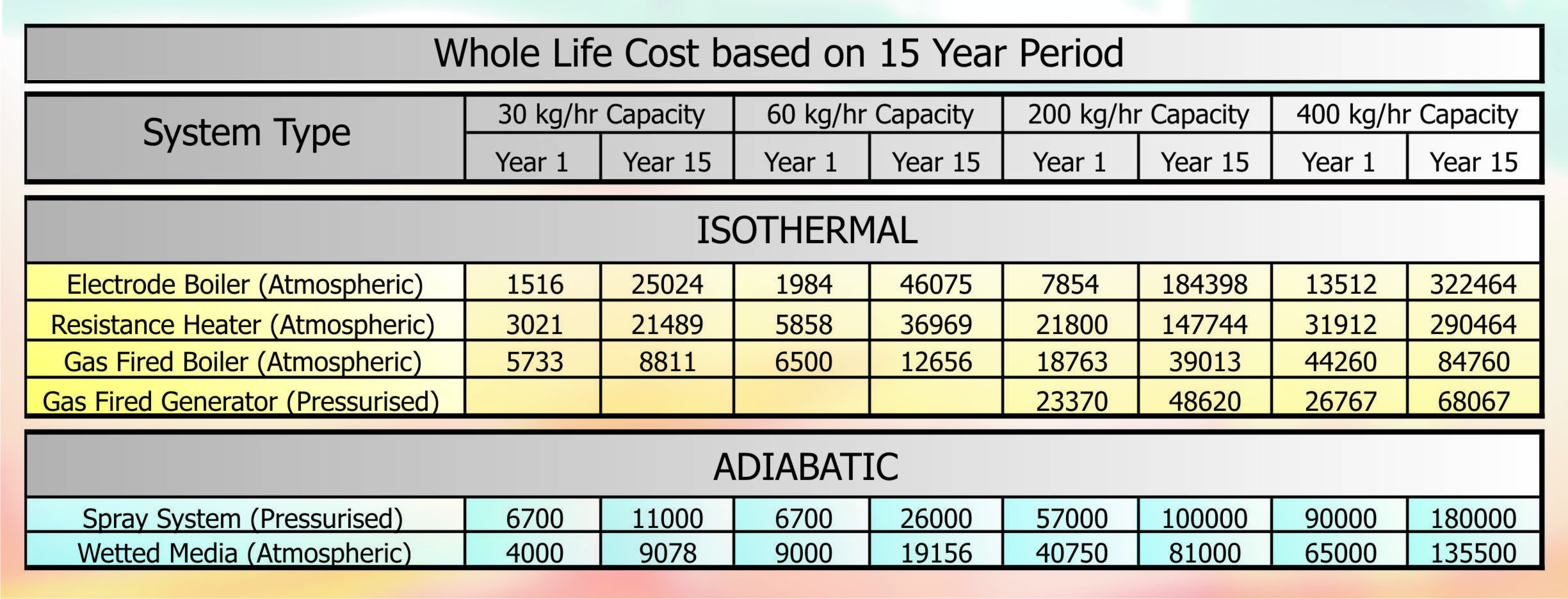
Fig 14 – Whole Life Cost
Water Quality
Through all this should be considered the incoming water supply. Water containing 500-PPM temporary hardness particles in suspension would precipitate approximately 0.1 kg/hr of scale or calcium deposit when heated and boiled of as steam. Assuming no water treatment for the cold water spray or ultrasonic system this value would still be relevant. Using the same hours run criteria as the comparative run cost we can be calculated that 135 kg (297 lb.) per annum of solid material would be collected in the boiler, if isothermal, or in the filter downstream of the spray if adiabatic. If no filter is fitted this dust would precipitate out onto the occupied workspace.
This is a startling statement as a reminder that it is better to treat the water for optimum performance in accordance with the humidification device fitted than to add cost to address a problem of our own creation.
NOTE: Our sincere thanks go to Mike Creamer of Business Edge Ltd. Re-creation of Drawings by Business Edge Ltd.
DISCLAIMER: Whilst every effort is made to ensure absolute accuracy, Business Edge Ltd. will not accept any responsibility or liability for direct or indirect losses arising from the use of the data contained in this series of articles.